R900561288 4WE6J6X-EG24N9K4

Introduction:
DIRECTIONAL SPOOL VALVE
R900561288
4WE6J6X/EG24N9K4
in stock. fast delivery
Manufacturer:Bosch Rexroth

| Direct actuated |
| Spool valve |
| Maximum flow (AC) 60 l/min |
| Maximum operating pressure 350 bar |
| Maximum flow (DC) 80 l/min |
| Size 6 |
| Component series 6X |
| Spool symbol | Symbol J |
| Max. pressure | 350 |
| Electrical connection description | Connector 3-pole (2 + PE) according to EN 175301-803 |
| Productgroup ID | 9,10,11,12,13,14 |
| Number of ports | 4 |
| Type of actuation | with solenoid actuation |
| Size | 6 |
| Electrical connector | Connector 3-pole (2 + PE) |
| Max. flow | 80 |
| Type of connection | Subplate mounting |
| Connection diagram NFPA | NFPA T3.5.1 R2-2002 D03 |
| Size_CETOP | D03 |
| Connection diagram | ISO 4401-03-02-0-05 |
| Supply voltage | 24 VDC |
| Number of switching positions | 3 |
| Weight | 1.99 |
| Seals | NBR |
| Hydraulic fluid | HL,HLP,HLPD,HVLP,HVLPD,HFC |
DIRECTIONAL SPOOL VALVE 4WE6J6X/EG24N9K4
Size 6, symbol J, electrical with solenoid, 24 V DC
Industrial hydraulic valve in a high performance range. Reliable switching of the oil flow direction according to hydraulic symbol.
Unpacked Weight: 1.99 kg
4/3-, 4/2- or 3/2-way version Porting pattern according to ISO 4401-03-02-0-05 (with or without locating hole) High-power solenoid, optionally rotatable by 90° Electric connection as single or central connection Optional auxiliary operating device Spool position monitoring, optional CE conformity according to the Low-Voltage Directive 2014/35/EU for electrical voltages >50 VAC or >75VDC Solenoid coil as approved component with UR marking according to UL 906, edition 1982, optional Approval according to CSA C22.2 no. 139-1982, optional
Directional valves type WE are solenoid-operated directional spool valves and can be used as electromagnetic components. They control the start, stop and direction of a flow.
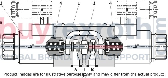
The directional valves essentially consist of the housing (1), one or two electromagnets (2), the control spool (3) and the return springs (4).
In the de-energized state, the control spool (3) is held in the middle or initial position by the return springs (4) (except version “O”).
When the electromagnet (2) switching in oil is energized, the control spool (3) moves from its rest position to the desired end position. This releases the required flow direction according to the selected symbol.
After switching off the electromagnet (2), the control spool (3) is pushed back to the middle or initial position (except for valve with detent “OF” and valve without spring type “O”).
An auxiliary actuation (5) enables the valve to be switched manually without magnet supply.
The hydraulic system must be properly vented to ensure proper function.
Without spring return “O” (only possible with symbols A, C and D)
This version is a directional valve with two switching positions and two electromagnets without detent. The valve without spring return on the control spool (3) has no defined basic position when de-energized.
Without spring return with detent “OF” (only possible for symbols A, C and D)
This version is a directional valve with two switching positions and two electromagnets with detent. The control spool (3) is fixed in the respective switching position by the detents. During operation, the permanent current supply to the electromagnet can thus be omitted, which contributes to energy-efficient operation.
Version “.73...A12” (soft switching behavior)
The composition of the control spools and solenoids greatly reduces the number of switching strokes that occur when the valves are switched on or off. The switching strokes, measured as acceleration values a, can be reduced by approx. 85 % compared to the standard valve, depending on the version of the control spool (see “Acceleration values”).
Notices:
Pressure peaks in the drain line to two or more valves may cause unintentional control spool movements in the version with detent. It is recommended to lay separate return lines or to install a check valve in the drain line.
Due to the design principle, the valves are subject to internal leakage, which can increase during the service life.
Type 4WE 6 E6X/...E...

Throttle insert
The use of a throttle insert is required when, due to prevailing operating conditions, flows occur during the switching processes which exceed the performance limit of the valve.


